Ductile Iron Duck Foot Bend: Riser Support Guide for Fire Systems
 By Mr. Xiao | Pipeline Systems Expert at Topsun | Updated for 2026
There is a specific type of failure that fire protection engineers in the Middle East encounter more often than they should. A high-rise building in Riyadh or Dubai has passed its fire suppression system commissioning test. The wet riser is charged, the pump station is operational, and the building handover proceeds. Twelve to eighteen months later, during a routine inspection or—worse—during a live emergency, a leak is discovered at the base of the riser. The vertical pipe has fractured at the point where it meets the horizontal distribution main, and the fracture pattern is unmistakable to anyone who knows what caused it: the joint has been subjected to sustained bending stress from an unsupported vertical load, combined with progressive micro-settlement of the pump plinth or floor slab beneath it.
This failure was not caused by a manufacturing defect. It was not caused by water hammer or system overpressure. It was caused by a design omission that is entirely preventable: the riser base was connected to the horizontal main without a ductile iron duck foot bend—the one fitting specifically engineered to transfer vertical pipe weight and hydraulic thrust loads directly to the structural floor, rather than allowing them to accumulate as bending stress at the pipe joint.
In 2026, as the Middle East continues to develop some of the world's most ambitious high-rise and mixed-use infrastructure—towers in excess of 300 meters, multi-basement pump stations serving combined fire and domestic systems, and fire hydrant assemblies designed for flows exceeding 2,000 liters per minute—the structural loading logic of the flanged duck foot bend is not a detail that can be left to the contractor to resolve on site. It must be in the design from the first layout drawing. This guide explains exactly why, and exactly how.
Table of Contents
The Structural Problem at Every Riser Base
What a Duck Foot Bend Actually Is
Force Analysis: What Loads Act on a Riser Base Joint
Duck Foot Bend vs. Standard Elbow: Why the Difference Matters
Specification and Sizing for Fire Protection and Pump Station Applications
Installation Positioning and Anchor Bolt Requirements
Middle East Project Considerations in 2026
Frequently Asked Questions (FAQ)
1. The Structural Problem at Every Riser Base
To understand why a duck foot bend is not optional at a riser base, you first need to be precise about what is happening mechanically at that location. A wet riser in a high-rise building is not just a pipe carrying water. It is a pressurized, water-filled column whose total weight increases with every floor it rises through. A DN150 wet riser filled with water in a 30-story building carries a static water column pressure of approximately 9 bar at its base—before any pump pressure is added. Add the pump delivery pressure of 5–7 bar for a typical high-rise fire system, and the joint at the riser base is experiencing combined internal pressure of 14–16 bar during a fire event.
But internal pressure alone does not cause the bending failure I described at the opening of this guide. The bending failure occurs because a filled, pressurized vertical riser also generates a significant vertical compressive load through the pipe wall itself—the dead weight of the water and iron above the base joint—and a horizontal thrust reaction at the 90-degree direction change where the riser meets the horizontal distribution main. These two forces act simultaneously on the joint at the riser base. If that joint is a standard flanged elbow bolted directly to the horizontal main, both forces are transferred entirely through the pipe wall and bolt group of that joint. Over time, under cyclic pressure surges from pump start-stop events and thermal expansion from ambient temperature cycling—a serious concern in the Middle East, where plant room temperatures can swing 30°C between night and peak day—the joint experiences fatigue loading that no standard elbow connection is designed to resist indefinitely.
The result is a crack. It starts small, often at the flange face weld fillet. It progresses invisibly. It becomes a leak at the worst possible moment.
2. What a Duck Foot Bend Actually Is
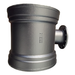
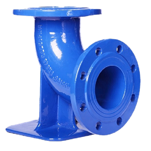
The ductile iron duck foot bend—formally catalogued as the Ductile Iron Double Flanged Duck Foot Bend Pipe Fitting—is a 90-degree direction-change fitting with an integral base plate cast onto the outlet flange face. The name comes from the visual profile of the fitting: seen from the side, the horizontal outlet flange with its cast base plate resembles the flat, splayed foot of a duck, projecting outward from the lower end of the vertical pipe run.
Structurally, the base plate transforms the fitting from a simple pipe direction-change component into a self-supporting structural element. The base plate is drilled with anchor bolt holes and sits flat on the pump room floor or structural plinth. When the anchor bolts are installed and grouted into the floor slab, the duck foot bend becomes a fixed point that:
Transfers the full vertical compressive load of the riser (pipe weight plus water weight plus any attached valves or instrumentation) directly to the structural floor—bypassing the pipe joints entirely.
Resists the horizontal thrust reaction at the 90-degree change of direction without relying on the bolt group of the adjacent flanged connection.
Provides a stable, level, and independently supported base from which both the vertical riser and the horizontal distribution main can be connected without imposing load on either pipe run.
The fitting body is manufactured from Grade 500-7 ductile iron per ISO 1083, providing a minimum tensile strength of 500 MPa and a minimum elongation of 7%—sufficient to absorb the impact loads from pressure transients (water hammer) that occur at pump start-up in high-rise fire systems without fracturing, which is the failure mode that grey cast iron fittings are historically susceptible to in exactly these applications.
3. Force Analysis: What Loads Act on a Riser Base Joint
For designers who need to justify the duck foot bend specification to a client or contractor who is questioning the cost, the following force breakdown provides the technical basis for the requirement. These are not theoretical worst-case scenarios—they are normal operating conditions for a typical DN150 wet riser in a Middle Eastern high-rise building.
| Load Type | Source | Approximate Magnitude (DN150, 30-story riser) | Direction at Riser Base |
|---|---|---|---|
| Static Water Column Pressure | Water height in riser (~90m for 30 floors) | ~9 bar at riser base | Radial (internal pressure on pipe wall and fittings) |
| Pump Operating Pressure | Fire pump delivery head | +5 to +7 bar during fire event | Radial (adds to static water column pressure) |
| Dead Weight of Riser | Weight of pipe + water + fittings above base | ~2,800–3,400 kg vertical compressive load | Vertical (downward) — concentrated at riser base joint |
| Hydraulic Thrust at 90° Bend | Pressure × cross-sectional area of pipe at change of direction | ~16 bar × 0.0177 m² = ~28 kN horizontal thrust | Horizontal (in direction of distribution main) |
| Water Hammer (Pressure Surge) | Rapid pump start-stop, valve closure | Up to 1.5–2× operating pressure as peak surge | Cyclic — all directions, fatigue loading on joints |
| Thermal Expansion / Contraction | Temperature swing in plant room (Middle East: up to 30°C) | ~0.6–1.0 mm axial movement per 10m pipe length per 10°C | Axial (both elongation and contraction cycles) |
A standard 90° elbow at the riser base, even a flanged ductile iron elbow rated for PN25, is designed to contain the radial internal pressure loads. It is not designed as a primary structural support for the 2,800–3,400 kg vertical compressive load of the riser above it, nor for the 28 kN horizontal thrust force at the change of direction. The duck foot bend, with its anchor-bolted base plate transferring these loads directly to the concrete floor structure, is the only fitting in the standard catalog that addresses all five load types simultaneously at the riser base node.
4. Duck Foot Bend vs. Standard Elbow: Why the Difference Matters
I want to address this comparison directly because it is the most common conversation I have when a contractor is looking to substitute a standard double flanged elbow for a duck foot bend on cost grounds. The cost difference between the two fittings at DN150 PN16 is modest in absolute terms—typically 15–25% more for the duck foot variant. What the contractor is not costing is the external pipe support structure that a standard elbow requires to achieve the same structural outcome.
| Comparison Factor | Ductile Iron Duck Foot Bend | Standard Double Flanged Elbow (90°) |
|---|---|---|
| Integral Floor Support | ✅ Yes — base plate with anchor bolt holes cast integral to fitting body | ❌ No — external steel support bracket or concrete cradle required as separate civil works item |
| Vertical Load Transfer to Structure | Direct — through base plate to floor anchor bolts | Indirect — through external bracket, which must be designed, fabricated, and installed as a separate activity |
| Horizontal Thrust Resistance | Provided by anchor bolt group in floor slab — no additional thrust block required | Requires either a concrete thrust block or a restrained joint on the adjacent horizontal pipe length |
| Settlement Resistance | Fixed to structural slab — moves with the building structure, not with the pipe network above | Movement of external support under differential settlement transfers directly to pipe joints as bending stress |
| Maintenance Access | Both flanged ends fully accessible for valve and fitting removal without disturbing the base support | Access to adjacent fittings may be restricted by external support steelwork |
| Total Installed Cost | Fitting cost + anchor bolts + non-shrink grout. No external steelwork or concrete block required. | Fitting cost + fabricated steel support bracket + concrete thrust block + additional civil works coordination. Total typically exceeds duck foot solution by 30–50%. |
When the full installed cost comparison is laid out this way, the substitution argument collapses. A duck foot bend is not a premium fitting—it is the most cost-efficient structural solution for the riser base node when the total civil and support works cost is properly accounted for.
5. Specification and Sizing for Fire Protection and Pump Station Applications
The Ductile Iron Double Flanged Duck Foot Bend Pipe Fittingfrom Topsun's catalog is available in the diameters and pressure ratings that cover the full range of fire protection and pump station riser applications encountered in Middle Eastern projects.
Pressure Rating
For fire protection wet risers and pump station delivery headers, the standard specification is PN16 (16 bar working pressure) to EN 1092-2 flange drilling, which provides an adequate safety margin over the combined static head plus pump pressure that even very tall buildings generate at the riser base. For buildings exceeding 40 stories, or for pump stations with variable speed drives delivering high transient pressures, PN25is the appropriate rating. Never specify PN10 for wet riser base applications regardless of the calculated static head—the water hammer surge allowance requires the higher pressure class.
Diameter Range
Duck foot bends are available from DN80 through DN600in the standard range. For fire protection wet risers in residential and commercial high-rise buildings, the most common specifications are:
DN80 / DN100: Domestic and light commercial wet risers, hose reel supply mains.
DN150: Standard wet riser for commercial high-rise, hotel, and mixed-use towers. Most common single specification in Middle Eastern projects.
DN200 / DN250: Combined fire and domestic water risers in large-footprint towers, or pump station delivery headers where multiple risers are supplied from a common main.
DN300 and above: Major pump station delivery headers in large-scale district cooling and fire ring main systems.
Flange Drilling Standard
For Middle Eastern projects, the default flange drilling standard is EN 1092-2 PN16 or PN25. Verify the flange drilling of the fire pump outlet flange and the isolation valve flanges adjacent to the duck foot bend before ordering—in projects with mixed European and American-supplied equipment, a mismatch between EN 1092-2 and ASME B16.5 drilling patterns at the pump outlet is more common than it should be.
6. Installation Positioning and Anchor Bolt Requirements
A duck foot bend that is correctly specified but incorrectly installed provides only partial protection against the riser base failure mode described at the opening of this article. The installation sequence and anchor bolt specification matter as much as the fitting selection itself.
Floor Level and Plinth Height
The duck foot bend base plate must bear directly on a level, structural concrete surface—either the pump room floor slab or a purpose-made concrete plinth. In Middle Eastern pump stations where floor drainage channels create changes in finished floor level, the duck foot bend must be positioned on a plinth high enough to maintain the correct centerline elevation of the horizontal distribution main connecting to the fitting outlet flange. The plinth must be structurally tied to the floor slab, not simply placed on it as a non-bonded block.
Anchor Bolt Specification
The anchor bolts fixing the duck foot bend base plate to the concrete structure must be sized to resist the combined vertical and horizontal loads calculated in Section 3 of this guide with an appropriate safety factor. For a DN150 PN16 duck foot bend in a 30-story fire riser application, M20 stainless steel chemical anchor bolts installed to the manufacturer's specified embedment depth in minimum C25 concrete are the standard specification. Galvanized mild steel anchor bolts are not acceptable in pump station environments where condensation and water splash create a high corrosion risk—a failed anchor bolt on a life-safety fitting is not a maintenance event, it is a structural incident.
Non-Shrink Grout Under Base Plate
After the anchor bolts are set and the duck foot bend is positioned, the gap between the base plate underside and the structural surface must be filled with non-shrink cementitious grout to 100% bearing contact. A base plate that bears on only two of its four corners—because the floor surface is not perfectly level and no grout has been applied—will rock under cyclic loading and will eventually fatigue the anchor bolts it depends on. This step is routinely omitted by contractors who have not been briefed on it. Make it a witness point in the inspection test plan for pump room pipework.
7. Middle East Project Considerations in 2026
The fire protection engineering environment in the Middle East has evolved significantly in the years leading up to 2026. The adoption of NFPA 14 (Standard for the Installation of Standpipe and Hose Systems) as the de facto reference code across Saudi Arabia, the UAE, Qatar, and Kuwait—alongside the regional civil defense authority codes—has brought a higher level of scrutiny to riser base structural details than was common in projects designed to older, less prescriptive local standards.
Civil defense authority inspection teams in the UAE and Saudi Arabia are increasingly flagging riser base installations that use standard elbows without integral floor support as non-compliant—requiring costly remediation works that delay occupancy certificates. The duck foot bend, when properly installed with documented anchor bolt specifications and grout inspection records, provides the paper trail that authority inspectors require to confirm that the riser base structural requirement has been addressed by engineering design rather than left to site judgment.
Additionally, in 2026, the combination of ultra-high-rise construction activity (multiple towers above 400 meters are under design or construction across the Gulf region) and the increasing use of variable speed fire pumps capable of delivering higher transient pressures than traditional constant-speed pump sets has made the water hammer surge allowance at riser bases a live design issue rather than a theoretical one. The PN25 pressure rating for duck foot bends in very tall buildings is no longer a conservative over-specification— it is a necessary engineering response to the actual dynamic pressures these systems generate during fire events.
8. Frequently Asked Questions (FAQ)
Q: Can a duck foot bend be used for a downward-facing vertical riser as well as an upward-facing one?
A: Yes. The duck foot bend is equally applicable at the base of a descending riser (where the pipe comes down from above and turns horizontal) and at the base of an ascending riser (where the pipe begins its vertical rise from a horizontal supply main). In both cases, the base plate provides the structural floor support and horizontal thrust resistance that the joint between vertical and horizontal pipe runs requires. Confirm the orientation with the fitting supplier—the base plate position is fixed relative to the fitting body and must be specified as either "riser ascending" or "riser descending" at the time of order to ensure the base plate is on the correct face of the fitting.
Q: Is a duck foot bend required at every floor where a fire hose reel or landing valve branches from the riser, or only at the riser base?
A: A duck foot bend is required specifically at the riser base—the point where the vertical riser transitions to the horizontal distribution main and where the maximum combined vertical and horizontal loads are concentrated. At intermediate floors where landing valves or hose reel connections branch from the riser, the riser is a continuous vertical column supported by floor bracket clamps at each level—these brackets carry the floor-by-floor pipe weight and do not require a duck foot bend. The duck foot bend addresses the unique structural condition at the base transition only.
Q: My project uses grooved-end (Victaulic-type) couplings throughout the fire system. Can a duck foot bend be supplied with grooved ends instead of flanged ends?
A: The standard ductile iron duck foot bend catalog is flanged-end only—the flanged connection at both the vertical and horizontal faces provides the rigid, bolt-secured interface that allows the fitting to function as a structural fixed point. Grooved couplings are inherently flexible joints and cannot provide the rigid load transfer that the duck foot bend base plate relies on. For systems using grooved couplings, the standard approach is to use a flanged duck foot bend at the riser base and transition to grooved couplings above and below it via short flanged-to-grooved adaptor spools. This arrangement preserves the structural function of the duck foot bend while maintaining compatibility with the grooved coupling system on the rest of the pipework.
Q: What is the internal coating specification for a duck foot bend used in a fire protection wet riser?
A: For fire protection wet risers carrying treated municipal water that also serves as potable water backup (a common arrangement in Middle Eastern buildings), the internal coating must be food-grade approved—either fusion-bonded epoxy (minimum 250 microns, NSF/ANSI 61 or equivalent compliant) or cement mortar lining to ISO 4179. Bituminous internal coating is not acceptable for systems where the water may be consumed. For dedicated non-potable fire systems, bituminous internal coating is acceptable but epoxy is still preferred for above-ground flanged fittings in plant rooms due to its superior resistance to the temperature cycling and condensation environment of a Middle Eastern pump room.
Q: How do I calculate the correct anchor bolt size for a duck foot bend installation, and does Topsun provide this calculation?
A: The anchor bolt sizing calculation requires the fitting's base plate dimensions and anchor hole pattern (provided in Topsun's fitting dimensional drawing), the combined vertical and horizontal loads from the specific riser height and operating pressure, and the structural engineer's confirmation of the floor slab concrete grade and embedment depth capacity. Topsun provides the fitting dimensional drawing with base plate geometry as standard documentation. The anchor bolt sizing calculation using these inputs should be performed by the project structural engineer or the mechanical engineer with access to the structural drawings. For projects where this calculation support is requested, our technical team can provide a load summary document for the specific fitting size and operating pressure to assist the structural engineer's calculation.
The ductile iron duck foot bend is one of the most structurally important fittings in any fire protection or pump station riser system—and one of the most frequently under-specified. In the Middle East's demanding combination of extreme building heights, high operating pressures, significant thermal cycling, and increasingly rigorous civil defense inspection requirements, specifying this fitting correctly from the earliest design stage is not a conservative choice. It is the only defensible engineering choice.
Specifying Duck Foot Bends for a Middle East Fire or Pump Station Project?
Topsun supplies ductile iron double flanged duck foot bends DN80–DN600 in PN16 and PN25 pressure ratings with EN 1092-2 flange drilling, epoxy internal coating, and full dimensional drawings for civil anchor coordination. Fast lead times to the Gulf region.
Request Drawings and Pricing WhatsApp Mr. XiaoMr. Xiao
Mr. Xiao is a senior pipeline systems expert at Shanghai Topsun Industrial Co., Ltd. He has provided fittings specification and supply support for fire protection and pump station projects across the Middle East, with particular experience in high-rise riser base structural detailing, flange standard compatibility for Gulf region projects, and civil defense authority documentation requirements in the UAE and Saudi Arabia.
National Fire Protection Association. NFPA 14: Standard for the Installation of Standpipe and Hose Systems, 2019 Edition.
European Committee for Standardization. EN 545: Ductile iron pipes, fittings, accessories and their joints for water pipelines — Requirements and test methods.
European Committee for Standardization. EN 1092-2: Flanges and their joints — Circular flanges for pipes, valves, fittings and accessories, PN designated — Cast iron flanges.
International Organization for Standardization. ISO 1083: Spheroidal graphite cast irons — Classification.
International Organization for Standardization. ISO 2531: Ductile iron pipes, fittings, accessories and their joints for water applications.
NSF International. NSF/ANSI Standard 61: Drinking Water System Components — Health Effects.