Ductile Iron Pipe Fittings Guide: Classification & Selection 2026
 By Mr. Xiao | Pipeline Systems Expert at Topsun | Updated for 2026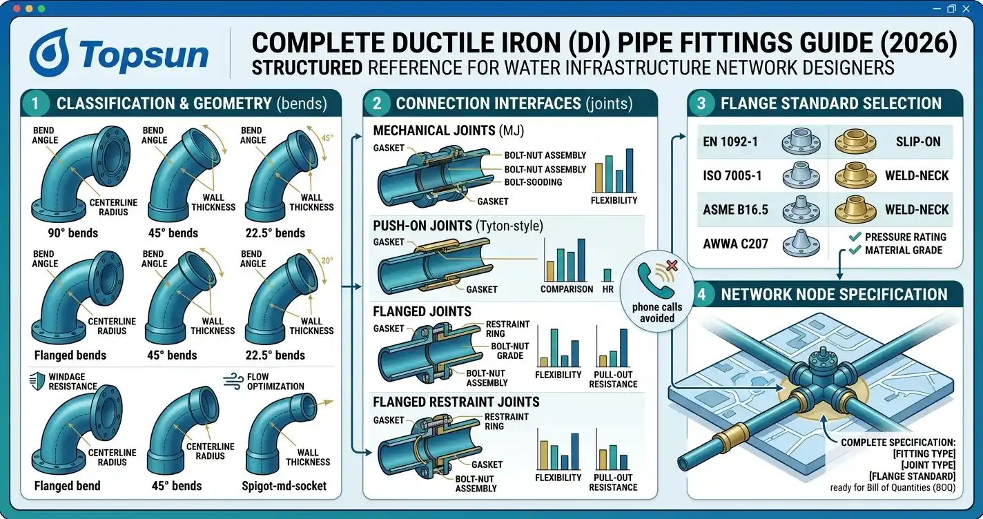
Every pipeline network designer I have worked with over the past fifteen years carries the same quiet frustration. The pipe specification is straightforward. The pressure class is defined. The standards reference is clear. But the moment the design reaches a node—a branch point, a diameter transition, a wall penetration, a pump station inlet—the fittings package becomes a maze of overlapping terminology, inconsistent catalog descriptions, and flange drilling patterns that may or may not match the valve supplier's facing standard.
A DN300 transmission main is simple. The tee, reducer, and bend assembly that connects it to a booster station is where projects quietly accumulate cost and delay—usually discovered not at the design stage but during installation, when the flanged adaptor from one supplier does not mate with the butterfly valve from another, and someone has to make an expensive phone call to explain why the commissioning date needs to move.
This ductile iron pipe fittings guide is written to eliminate that phone call. It is a structured, classification-first reference for pipeline network designers working on water supply, drainage, and treatment infrastructure in 2026—covering the fullDI fittings catalog from bend geometry through connection interface through flange standard selection, so that every node in your network design is specified completely and correctly before the Bill of Quantities is issued.
Table of Contents
How the DI Fittings Classification System Works
Bend Fittings: Geometry, Angles, and Application Logic
Tee Fittings: Branch Node Design for Water Networks
Reducer Fittings: Diameter Transitions in Pressurized Mains
Flange Standards and Interface Compatibility
Puddle Flanges and Structure Penetration Fittings
Connection Interfaces: Socket, Spigot, Flanged, and Loose Flange
Internal and External Coating Selection for Fittings
Frequently Asked Questions (FAQ)
1. How the DI Fittings Classification System Works
Ductile iron fittings are classified by three parameters that must all be specified simultaneously. Miss any one of them and the fitting cannot be correctly manufactured, priced, or installed. These three parameters are: body geometry (what shape the fitting is), end connection type (how each end connects to the adjacent pipe or fitting), and protective coating(internal lining and external finish). A fitting description that specifies only geometry is an incomplete specification—the equivalent of ordering a pipe without specifying a pressure class.
The governing standards for ductile iron fittings in water and sewerage applications are ISO 2531, EN 545 (for potable water), and EN 598 (for sewerage). All three standards address dimensional tolerances, mechanical properties, and minimum coating requirements. In practice, most global infrastructure tenders accept either ISO 2531 or EN 545 for water fittings—but the designer must make that choice explicitly in the specification, because the two standards differ in their flange drilling reference standards and coating requirements, as we will address later in this guide.
2. Bend Fittings: Geometry, Angles, and Application Logic
Bend fittings redirect the pipeline axis through a defined angle. In a ductile iron water pipe fittings system, the standard bend angles are 11.25°, 22.5°, 45°, and 90°, and any intermediate deflection can be composed from combinations of these standard angles. The choice of bend angle is a hydraulic and spatial decision, not simply a geometric one.
Double Socket Bends
The Ductile Iron Double Socket Bend Pipe Fitting is the standard underground bend for push-on jointed pipe networks. Both ends are socketed, accepting spigot ends from adjacent pipes or fittings. Double socket bends are the most hydraulically efficient bend configuration because the flow transition through the socket geometry is gradual, reducing turbulence at the change of direction. They are available with epoxy or bituminous external coating, depending on soil aggressivity.
Double Flanged Bends
The ISO2531 Ductile Iron Double Flanged 45°/90° Bend Pipe Fitting for Water Supply is specified for above-ground installations, pump stations, water treatment plant pipework, and any location where the fitting must be dismountable for maintenance access. Both ends carry integral flanges drilled to a specified standard (typically EN 1092-2 for European-compliant projects). Double flanged bends create a rigid, zero-deflection connection and require flanged isolation between each pipe length for expansion and contraction management in exposed environments.
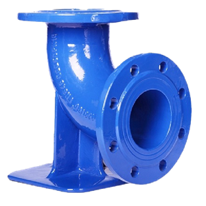
Duck Foot Bends
The Ductile Iron Double Flanged Duck Foot Bend Pipe Fitting is a specialized 90° bend with an integral base plate at the outlet flange face. It is used specifically at pump station delivery outlets, vertical riser connections, and locations where the pipeline transitions from horizontal to vertical orientation, and the fitting must be self-supporting on a concrete plinth without external pipe supports. The base plate transfers the pipe weight and hydraulic thrust directly to the foundation structure.
| Bend Type | Standard Angles | Primary Application | Installation Environment |
|---|---|---|---|
| Double Socket Bend | 11.25° / 22.5° / 45° / 90° | Underground distribution and transmission mains | Buried — push-on joint network |
| Double Flanged Bend | 45° / 90° | Pump stations, treatment plant pipework, above-ground risers | Above ground — flanged joint network |
| Duck Foot Bend | 90° (fixed) | Vertical-to-horizontal transitions at pump outlets and valve chambers | Above ground — self-supporting on concrete base |
3. Tee Fittings: Branch Node Design for Water Networks
Tee fittings create branch connections from a main pipeline to a secondary or distribution line. In a complex network, the tee specification is the most variable element in the fittings schedule because each of the three ends may carry a different connection type, and a mistake in any one end interface creates a non-installable fitting.
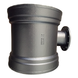
Double Socket Tee with Flanged Branch
The Ductile Iron Double Socket Tee with Flanged Branch is the workhorse branching fitting for underground distribution networks that connect to above-ground isolation valves. The two run ends (inlet and outlet of the main flow path) are socketed, maintaining continuity with the push-on joint pipe network. The branch end carries an integral flange, allowing a flanged gate valve or butterfly valve to be bolted directly to the tee without an intermediate adaptor piece.
This configuration is particularly valuable in municipal networks where gate valves are installed at regular intervals for zone isolation. The flanged branch allows the valve to be removed for maintenance or replacement without disturbing the buried push-on pipe joints on either side of the tee—a significant operational advantage over an all-socket tee configuration that would require cutting into the pipe to access the valve.
Tee Selection Matrix for Network Designers
| Network Scenario | Recommended Tee Type | End Connection Configuration |
|---|---|---|
| Underground main with buried branch pipe continuation | All-socket tee (equal or reducing) | Socket × Socket × Socket |
| Underground main with above-ground isolation valve on branch | Double Socket Tee with Flanged Branch | Socket × Socket × Flanged Branch |
| Treatment plant inlet manifold, fully flanged pipework | All-flanged tee (equal or reducing) | Flanged × Flanged × Flanged |
| Transition point from buried push-on main to above-ground flanged valve chamber | Push-on Tyton Joint Flanged Socket Fitting | Socket (push-on entry) × Flanged (chamber exit) |
4. Reducer Fittings: Diameter Transitions in Pressurized Mains
Reducer fittings manage the transition between two pipe diameters within the same pressurized system. In water supply network design, diameter transitions occur at three common locations: at the boundary between transmission mains and distribution mains, at pump station discharge headers where multiple pump outputs converge into a single larger main, and at individual service connections where a DN200 main branches to a DN80 or DN100 domestic supply lateral.
Double Flanged Taper Reducers
The Ductile Iron Double Flanged Taper Reducer EN545/EN598/ISO2531 with Epoxy Coating is the standard reducer for above-ground and treatment plant applications. The concentric taper geometry produces a smooth, gradual velocity change between the two diameters, minimizing the head loss at the transition point. In pump station design, head loss at fittings is not a secondary consideration—every unnecessary meter of head loss translates directly into pumping energy cost over the life of the station.
Eccentric reducers (where one side of the reducer is flat rather than tapered concentrically) are specified when air entrainment at the transition point is a design concern. A concentric reducer installed with the pipe axis horizontal creates a high point at the top of the smaller inlet where air can accumulate. An eccentric reducer installed with the flat side up keeps the crown of both pipe diameters at the same elevation, allowing air bubbles to pass through without trapping.
5. Flange Standards and Interface Compatibility
Of all the specification decisions in a ductile iron fittings schedule, flange standard compatibility causes the greatest number of installation problems on global infrastructure projects. The reason is straightforward: ductile iron pipe fittings are typically sourced from one supplier, valves from a second, and flow meters from a third—and each supplier may default to a different flange drilling standard unless the specification is explicit.
In 2026, the dominant flange standards you will encounter across global water infrastructure projects are as follows.
| Standard | Primary Market | Common Pressure Ratings | Key Note |
|---|---|---|---|
| EN 1092-2 | Europe, Africa (EU-funded projects), Middle East | PN10 / PN16 / PN25 / PN40 | Default standard for EN 545 / EN 598 ductile iron fittings. PN16 is the most commonly specified rating for municipal water. |
| ISO 7005-2 | International / Asia / Africa (ISO-specified projects) | PN10 / PN16 | Closely aligned with EN 1092-2 for most common diameters and pressure ratings. Verify bolt circle diameter (BCD) against valve supplier drawings for DN ≥ 400. |
| ANSI / ASME B16.1 | Americas, some Asian markets with US engineering influence | Class 125 / Class 250 | Class 125 cast iron flange drilling is widely used in South American water projects. Not interchangeable with EN 1092-2 PN16 without a dimensional check—bolt circle diameters differ at multiple DN sizes. |
| AS 4087 | Australia, Pacific Islands | PN16 / PN21 / PN35 | Australian water authorities mandate AS 4087 compliance. Flange face finish requirements differ from EN 1092-2— specify raised face vs. flat face explicitly. |
The single most important instruction I give to every design engineer I brief: do not assume that EN 1092-2 PN16 and ISO 7005-2 PN16 are dimensionally identical at your specific diameter. For DN80 through DN300 they are effectively interchangeable. Above DN300, the bolt circle diameter and bolt hole count begin to diverge between standards for certain pressure ratings. Always cross-check the actual flange drawing against the valve supplier's flange face drawing before finalizing the fitting specification.
6. Puddle Flanges and Structure Penetration Fittings
Every pipeline that passes through a concrete wall, floor slab, or embankment dam requires a puddle flange fitting at the penetration point. This is a non-negotiable structural waterproofing requirement and one that is frequently omitted from early-stage fittings schedules by designers who are focused on the pipeline hydraulics rather than the civil interface details.
A puddle flange is an integral circumferential collar cast onto the pipe or fitting body, positioned so that when the pipe is cast into the concrete structure, the collar is fully embedded. The collar acts as a mechanical key that prevents the pipe from being pushed or pulled through the wall under pressure or settlement loads, and it also interrupts the potential seepage path along the annular gap between the pipe exterior and the concrete structure.
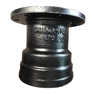
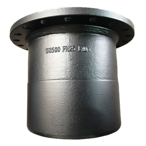
Flanged Spigot with Puddle Flange
The ISO2531/EN545/EN598 Ductile Iron Flanged Spigot Pipe Fitting with Puddle Flange for Potable Water is the standard penetration fitting for water treatment plant walls, reservoir inlet and outlet structures, and pump station wet well penetrations. One end carries an integral flange (for connection to the above-ground pipework inside the structure), and the opposite end is a plain spigot (for push-on joint connection to the buried pipeline outside the structure). The puddle flange collar is positioned centrally on the fitting body to be cast into the wall thickness.
Double Flanged Pipe with Puddle Flange
The Ductile Iron Double Flanged Pipe Fitting with Puddle Flange for Water Treatment Plant is specified where both sides of the wall penetration connect to flanged pipework—for example, a fully flanged treatment plant inlet header that continues as flanged pipework on both the raw water intake side and the treatment process side. Both ends carry drilled flanges, with the puddle collar again cast centrally into the wall.
7. Connection Interfaces: Socket, Spigot, Flanged, and Loose Flange
For a pipeline network designer, the connection interface at each end of every fitting is as important as the fitting body geometry. There are four interface types in the standard DI fittings catalog, and each has a specific application logic.
Socket (Bell) End
Accepts the plain spigot end of an adjacent pipe or fitting via the push-on Tyton gasket joint. Used for underground push-on joint networks. The socket end is always the receiving end—it cannot be pushed into another socket.
Spigot End
The plain, chamfered end that inserts into a socket. In fittings, spigot ends are used where a fitting must connect directly into an existing socket on the pipeline without an intermediate pipe length. The Ductile Iron Push-on (Tyton) Joint Flanged Socket Pipe Fittingcombines a spigot end on one side (for push-on connection to the buried main) with a flanged socket on the other (for above-ground valve or chamber connection)—a transitional fitting that bridges the buried push-on network and the above-ground flanged system at a single component.
Integral Flanged End
A flange cast integrally with the fitting body. The flange face is machined flat, drilled to a specified bolt pattern, and mated to an identical flange on the adjacent component using bolts, nuts, and a flat or raised face gasket. Integral flanges are the rigid, dismountable connection for above-ground pipework.
Loose Flange (Backing Ring)
The EN545/ISO2531 Ductile Iron Loose Flange Fitting for DI Pipeuses a separate steel or ductile iron backing ring that slides over the spigot end of the pipe before the connection is made. The ring is then used as the bolting face, with the spigot end belled out to retain the ring. Loose flanges allow the bolt holes to be rotated freely before bolting up, which is invaluable when connecting to a mating flange where the bolt hole orientation cannot be pre-determined—for example, when connecting to existing installed valves or to equipment with fixed flange orientations. They also accommodate minor axial misalignment that a rigid integral flange cannot tolerate.
| Interface Type | Dismountable? | Angular Flexibility | Typical Use Case |
|---|---|---|---|
| Socket (Push-on) | Yes (with pull-out tool) | Up to 5° deflection | Underground buried mains, push-on joint networks |
| Spigot (Plain End) | Yes (inserts into socket) | Per Tyton joint (≤5°) | Transition fittings, direct insertion into existing sockets |
| Integral Flange | Yes (bolted) | Zero — rigid connection | Above-ground pipework, pump stations, treatment plants |
| Loose Flange (Backing Ring) | Yes (bolted + rotatable before tightening) | Minor axial offset accommodation | Connection to existing valves, equipment with fixed flange orientations, field adjustment situations |
8. Internal and External Coating Selection for Fittings
Fittings coatings follow the same logic as pipe coatings but with one important distinction: fittings have more complex internal geometry than straight pipes, which means poorly applied coatings in fittings are far more common than in pipes—and far harder to detect during goods-received inspection.
Internal Coatings
Cement Mortar Lining (ISO 4179): Standard for socket-end fittings in underground water supply networks. Applied by spinning for straight sections; hand-applied in internal curves and socket zones. Inspect socket interiors specifically—the mortar in sharp internal bends is the area most likely to be thin or cracked.
Epoxy Coating (minimum 250 microns, fusion-bonded or liquid-applied): Mandatory for flanged fittings in water treatment plants and pump stations where the complex internal geometry of a tee or reducer body makes uniform cement mortar application impractical. Also used in all fittings where the water chemistry is too aggressive for cement (very low TDS, pH below 6.5).
Bituminous Coating: Acceptable as an internal coating for non-potable water and drainage applications only. Not approved for drinking water networks under WHO guidelines or EN 545 requirements.
External Coatings
Zinc spray + bituminous paint: Standard for all underground fittings. The same self-protecting galvanic mechanism as on straight pipe lengths—zinc corrodes preferentially to protect the iron body if the surface is scratched during handling or installation.
Epoxy coating (external): Specified for above-ground fittings in pump stations and treatment plants, where bituminous paint appearance is unacceptable and surface finish color coding (blue for potable water, green for raw water, red for fire) is required by the project specification. The Ductile Iron Double Flanged Taper Reducer EN545/EN598/ISO2531 with Epoxy Coating is a standard example of this coating combination for treatment plant applications.
9. Frequently Asked Questions (FAQ)
Q: Can I mix socket-end and flanged-end fittings from different manufacturers on the same project?
A: For socket-end fittings, mixing manufacturers is generally acceptable provided both conform to the same ISO 2531 or EN 545 dimensional standard, because the socket and spigot dimensions are standardized. For flanged fittings, mixing manufacturers is acceptable only if both reference the same flange standard (e.g., both to EN 1092-2 PN16) and you verify the bolt circle diameter and bolt hole count match at your specific DN and PN rating. Never assume compatibility—always request and compare actual flange drawings from both suppliers before mixing.
Q: What is the difference between a reducing tee and a double socket tee with flanged branch in terms of hydraulic performance?
A: The hydraulic difference is minor for most municipal flow velocities (below 2 m/s). Both fittings generate a local head loss at the branch junction that is expressed as an equivalent pipe length coefficient (K-value) in hydraulic modelling software. The more important practical difference is operational: a tee with a flanged branch allows a valve to be installed directly on the branch without additional adaptor fittings, which reduces the number of joints at the branch node and simplifies the valve chamber layout.
Q: My project specification says EN 545 for pipes but does not specify a standard for fittings. What should I default to?
A: Default to EN 545 for water supply fittings and EN 598 for sewerage fittings. These standards cover the same product family as the corresponding pipe standards and share the same flange drilling reference (EN 1092-2). Specifying fittings to EN 545 when the pipes are EN 545 ensures a consistent compliance documentation chain for the consultant's technical approval process—critical for EU-funded or European-consultant-managed projects where split-standard submittals are routinely rejected.
Q: Are puddle flange fittings always custom-manufactured, or are they available from standard catalog?
A: Standard puddle flange fittings in common configurations (flanged spigot with puddle collar, double flanged with puddle collar) are available from Topsun's standard product range for DN80 through DN600. The puddle collar position and diameter are standardized for typical wall thicknesses of 200mm to 500mm. For non-standard wall thicknesses, longer overall fitting lengths, or unusual collar positions required by structural engineering constraints, custom manufacturing is required with a lead time of approximately 4–6 weeks beyond standard production. Always confirm the wall thickness and collar position with the civil engineer before placing the fittings order.
Q: When should I specify a loose flange instead of an integral flanged fitting?
A: Specify a loose flange when you cannot guarantee bolt hole alignment between the ductile iron fitting and the mating component before the fitting is installed—for example, when connecting to existing valves already installed in a chamber, or when connecting to imported equipment where the flange face orientation is fixed by the equipment design. Loose flanges are also preferred for large-diameter fittings (DN ≥ 500) in treatment plants, where a slight axial misalignment between two flanged components would create unacceptable bending stress on an integral rigid flange but can be accommodated by the rotational freedom of a loose backing ring.
A complete and correctly cross-referenced ductile iron pipe fittings guide is the difference between a fittings schedule that flows smoothly through procurement, manufacture, customs, and site installation—and one that generates a series of non-conformance reports that cost the project weeks and the contractor real money. The classification framework in this guide covers the full range of fittings that Topsun supplies under our DI fittings catalog, and our technical team is available to review your project-specific fittings schedule before you issue it for tender.
Need a Complete DI Fittings Package for Your Water Network Design?
Topsun supplies ISO 2531 and EN 545 certified ductile iron fittings— bends, tees, reducers, puddle flange fittings, loose flanges, and transition pieces—to water and drainage projects worldwide. Our technical team can review your fittings schedule and identify specification gaps before you go to tender.
Submit Your Fittings Schedule for Review WhatsApp Mr. XiaoMr. Xiao
Mr. Xiao is a senior pipeline systems expert at Shanghai Topsun Industrial Co., Ltd. He has provided fittings specification support for water supply and drainage infrastructure projects across Africa, the Middle East, Southeast Asia, and South America, with particular expertise in flange standard compatibility, puddle flange civil interface coordination, and complex node fittings schedule development.