Ductile Iron Loose Flange Fitting: Solving Bolt Misalignment on Site
 By Mr. Xiao | Pipeline Systems Expert at Topsun | Updated for 2026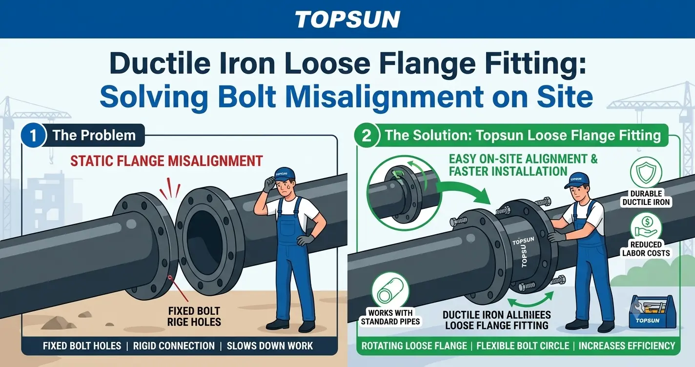
Every pipeline installation and maintenance crew has lived through this moment. The new flanged fitting is in position. The valve on the adjacent spool is already bolted down. Two workers lower the fitting into place, bring the flange faces together—and the bolt holes do not line up. Not by much. Maybe 15 degrees of rotational offset. Maybe 25. But enough that not a single bolt can be inserted without forcing the flange face out of alignment, which will compromise the gasket seal.
On a new-build project with access to a fabrication workshop and a full day of schedule buffer, this is a problem that gets solved with a pipe spool adjustment or a revised survey. On a live pipeline repair in a cramped valve chamber under a street in Warsaw or a pump station basement in Ho Chi Minh City, with the water main isolated, residents waiting, and the network operator calling for an update every thirty minutes—it is a crisis.
The technical solution to this crisis has existed for decades, and it costs less than the first hour of overtime your crew will spend trying to force an integral flange into alignment: the ductile iron loose flange fitting. In 2026, as aging pipeline infrastructure across Eastern Europe and Asia enters accelerated maintenance and replacement cycles, this fitting is one of the most practically valuable components in the repair and rehabilitation toolkit—and one of the most consistently under-specified by engineers who have never had to explain a blown schedule to a network operator from inside a flooded valve chamber.
This guide explains exactly how the loose ring flange works mechanically, when it is the correct specification choice over an integral flanged fitting, and how installation crews can use it to absorb the rotational tolerancing errors that real-world pipeline repair almost always produces.
Table of Contents
The Mechanics of a Loose Flange Fitting — What Makes It Different
Why Bolt Hole Misalignment Is So Common on Repair Projects
Loose Flange vs. Integral Flange: When to Specify Which
The Rotational Tolerance Advantage: What the Numbers Mean in Practice
Material and Pressure Rating Specification for Eastern European and Asian Projects
Installation Procedure: Getting the Loose Ring Right Every Time
Common Mistakes That Turn a Simple Fix into a Leak
Frequently Asked Questions (FAQ)
1. The Mechanics of a Loose Flange Fitting — What Makes It Different
To understand why a loose flange fitting solves the bolt hole misalignment problem, you need to be clear about what is different between it and a standard integral flanged fitting at the mechanical level. The difference is not cosmetic—it is a fundamental change in how the bolting force and the pipe end thrust load are distributed between the fitting and the adjacent component.
In an integral flanged fitting, the flange is cast as one body with the fitting. The bolt holes are machined at fixed positions relative to the fitting body. This means that the rotational orientation of the bolt hole pattern is permanently fixed at the moment of manufacture. If the mating flange on site has a different rotational orientation—because the adjacent pipe was not installed with the flange clock position verified, or because an old valve was replaced with a new one with a different hole pattern clock position—there is no mechanical adjustment available. You either rotate the entire fitting (which may not be possible if adjacent piping is already connected) or you elongate the bolt holes (which is a structural compromise and a maintenance-protocol violation in most regulatory frameworks).
In a ductile iron loose flange fitting, the flange is a separate component—a steel or ductile iron backing ring called the loose ring flange—that slides freely over the pipe or fitting spigot end before the connection is made. The spigot end is machined with an upset face (a belled-out retaining collar) that prevents the ring from sliding off after installation, but allows it to rotate freely through 360 degrees before the bolts are tightened. This free rotation means the bolt hole pattern of the loose ring can be aligned to exactly match the bolt hole pattern of the mating flange—regardless of the rotational position of the fitting body behind it.
The pressure thrust load at the joint is carried by the upset face of the spigot bearing against the back face of the loose ring. The bolts carry the gasket compression force only—they do not carry the longitudinal pipe thrust, which is a meaningful structural distinction from a bolted rigid flange joint where the bolt group carries both gasket compression and pipe thrust simultaneously.
2. Why Bolt Hole Misalignment Is So Common on Repair Projects
New-build pipeline projects have the advantage of controlling every flanged connection from the first installation. Repair and rehabilitation projects inherit the accumulated installation tolerancing errors of every previous crew that worked on the system—sometimes going back 30, 40, or 50 years. In Eastern European cities where much of the municipal water infrastructure was installed between the 1960s and 1980s under construction practices that prioritized speed over precision, and in rapidly developed Asian cities where infrastructure was expanded in multiple phases by multiple contractors with inconsistent survey control, the alignment conditions a repair crew encounters are rarely what the drawings show.
There are six specific scenarios that create bolt hole misalignment on repair and rehabilitation projects. Understanding which scenario you are in determines the correct specification response.
Scenario One — Pipe Settlement and Axial Rotation
Over decades of service, buried pipelines settle differentially depending on local soil conditions. A flanged valve or spool piece that was installed with perfectly aligned bolt holes may have rotated axially by 10–30 degrees as the surrounding soil consolidated unevenly around the pipe barrel. The pipeline has not failed—but the flanged connection has rotated to a position where the bolt holes no longer match those of an identically specified replacement component.
Scenario Two — Mixed-Era Component Replacement
Older pipeline systems in Poland, the Czech Republic, Romania, and their neighbors were often originally installed to COMECON-era Soviet metric flange standards (GOST 12815 series) that differ subtly from modern EN 1092-2 bolt hole counts and pitch circle diameters. When a modern EN-standard valve is inserted as a replacement into a GOST-standard pipeline, the bolt hole count matches at some diameters and pressure ratings—but the clock position of the bolt holes does not, because the number of holes is identical but their angular spacing is derived from slightly different pitch circle standards. A loose ring flange drilled to the modern EN standard, fitting over a locally machined or EN-converted spigot, allows the bolt holes to be clocked to align with the existing GOST-standard mating flange bolt holes.
Scenario Three — Pipe Centerline Survey Error
In confined valve chambers and pump station basements, the surveyed centerline of the pipeline as-built often differs from the design centerline by enough to create significant flange face angular misalignment—particularly on the branch connections of tee fittings, where a small positional error in the main pipe installation translates to a large angular error at the branch outlet flange. A loose ring flange on the branch outlet accommodates this angular error without requiring the fitting to be repositioned.
Scenario Four — Thermal Expansion Ratcheting
In pump stations and above-ground pipework in facilities with significant daily temperature cycling—common in Asian climates where plant room temperatures swing from 15°C at night to 45°C at peak afternoon conditions—the cumulative effect of repeated thermal expansion and contraction cycles can ratchet flanged connections out of their original bolt hole alignment over years of operation. When these connections are opened for maintenance, the bolt holes in the loosened flange no longer align with their original position.
Scenario Five — Replacement with Metric/Imperial Mismatch
In Southeast Asian countries with mixed infrastructure heritage— Vietnam, Indonesia, the Philippines, and others—pipeline systems may include components from Japanese (JIS B 2220), European (EN 1092-2), and American (ANSI B16.5) flange standards installed by different contractors across different project phases. A loose ring flange allows the repair crew to fit a new ductile iron fitting to a mating flange of any drilling standard, simply by drilling the loose ring to match the mating flange's bolt circle rather than a fixed manufacturing standard.
Scenario Six — Confined Space Rotation Constraint
In deep valve chambers and underground pump stations, it may be physically impossible to rotate a flanged fitting body once it has been lowered into position—because the adjacent pipework, chamber walls, or structural beams prevent rotation of the fitting beyond a few degrees. A loose ring flange allows the fitting body to be fixed in the only orientation that fits the space, while the loose ring is rotated independently to align with the mating flange bolt holes.
3. Loose Flange vs. Integral Flange: When to Specify Which
| Project Condition | Loose Flange Fitting | Integral Flanged Fitting |
|---|---|---|
| Existing mating flange clock position is unknown or unverified | ✅ Recommended — 360° ring rotation absorbs any clock position error | ⚠️ Risk — if bolt holes do not align, fitting must be returned or bolt holes elongated |
| Mating flange is a different drilling standard (e.g., GOST vs. EN 1092-2, or JIS vs. ANSI) | ✅ Ideal — loose ring can be custom-drilled to any standard to match the existing mating flange | ❌ Not suitable without custom machining of the fitting body flange — expensive and slow |
| Confined space prevents fitting rotation after positioning | ✅ Ideal — fitting body locked in position; ring rotated independently for bolt hole alignment | ❌ Not suitable — bolt hole alignment requires rotating the entire fitting body |
| New-build project with verified flange clock positions and same drilling standard throughout | ⚠️ Acceptable but over-specified — loose ring provides no additional benefit if clock positions are controlled | ✅ Standard choice — simpler, slightly lower profile, and fully adequate when alignment is controlled |
| Above-ground pipework requiring frequent disassembly for maintenance | ✅ Preferred — loose ring can be repositioned for bolt access if space constraints change after installation | ✅ Also acceptable — if bolt access space is confirmed adequate at design stage |
| Mixed-era rehabilitation project with multiple unknown existing flange standards | ✅ Strongly recommended as default — provides maximum field flexibility without re-ordering risk | ❌ High re-order risk — fitting may arrive with wrong bolt hole pattern for the actual site condition |
4. The Rotational Tolerance Advantage: What the Numbers Mean in Practice
The phrase "360-degree rotational freedom" sounds straightforward, but the practical implication for a repair crew is worth quantifying specifically. Consider a DN200 PN16 flanged connection with 8 bolt holes equally spaced at 45-degree intervals (the standard EN 1092-2 bolt hole pattern for this size and rating).
With an integral flanged fitting, the maximum rotational misalignment that can still be accommodated—by allowing the bolt to sit slightly off-center in its hole—is approximately ±3 degrees from the nominal hole centerline before the bolt head begins to bear on the flange face rather than sitting cleanly through the hole. In practice on a repair site, achieving ±3 degrees of rotational accuracy between a new fitting and an existing flange on an old, settled pipeline requires precise survey measurement of the existing flange clock position and careful installation control. It is achievable. It is also frequently not achieved, and the failure mode when it is not achieved ranges from time-consuming to schedule-catastrophic depending on the site conditions.
With a ductile iron loose flange fitting using a loose ring flange on one or both ends, the required rotational accuracy between the fitting body and the existing flange drops to zero. The ring simply rotates until all eight bolt holes align, and then the bolts are inserted. On a DN200 8-hole flange, this means any one of the eight bolt holes can be positioned at the 12 o'clock position—the ring accepts 45-degree increment alignment with the same ease as 1-degree increment alignment. For a repair crew working under time pressure in a confined space, this is not a marginal improvement in installation efficiency. It is the elimination of an entire category of field problem.
5. Material and Pressure Rating Specification for Eastern European and Asian Projects
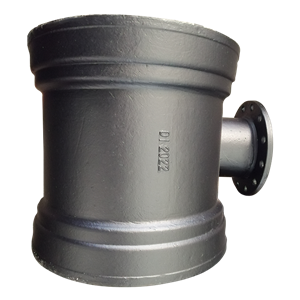
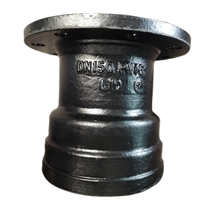
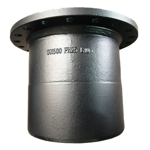
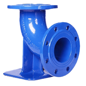
The EN545/ISO2531 Ductile Iron Loose Flange Fitting for DI Pipeis available in a range of configurations that cover the full spectrum of repair and rehabilitation scenarios encountered in Eastern European and Asian water infrastructure projects.
Loose Ring Material Options
The loose ring itself—the rotating backing plate—can be manufactured in three materials depending on the corrosion environment and the project's material specification requirements.
| Ring Material | Corrosion Resistance | Typical Application | Notes |
|---|---|---|---|
| Carbon Steel (S235 / S275) | Low — requires hot-dip galvanizing or paint coating for buried or wet environments | Above-ground dry environments; indoor valve chambers with controlled humidity | Lowest material cost. Standard choice for indoor above-ground applications in Eastern European utility budgets. |
| Ductile Iron (Grade 500-7) | Moderate — requires zinc + epoxy or bitumen external coating for buried service | Buried service; wet valve chambers; general water supply rehabilitation | Most common specification for water supply rehabilitation in Eastern Europe and Asia. Compatible with standard ductile iron system coatings. |
| Stainless Steel (316L) | Excellent — no external coating required in most service environments | Highly aggressive soils; marine and coastal locations; desalination plant pipework; high-humidity tropical environments | Highest material cost but eliminates ring corrosion risk in aggressive environments. Increasingly specified in Southeast Asian coastal infrastructure projects. |
Pressure Rating Selection
For water supply rehabilitation projects in Eastern Europe, the dominant pressure ratings encountered are PN10 and PN16 in EN 1092-2 or equivalent GOST metric ratings. For pump station delivery headers and high-pressure zones in Asian municipal systems—particularly in hilly cities where gravity-fed mains generate high static heads—PN25may be required. The critical specification point is that the loose ring must be rated to the same pressure class as the fitting body it is assembled with. A PN16 fitting body with a PN10 loose ring is not a PN16 joint—the limiting pressure rating of the assembly is the lower of the two components.
Diameter Range
Standard loose flange fittings for water supply rehabilitation are available from DN80 through DN600, covering virtually all distribution and transmission main diameters encountered in Eastern European and Asian municipal water networks. For larger diameters (DN700 and above) on transmission mains, custom fabricated loose ring assemblies may be required—confirm availability and lead time with Topsun's technical team for diameters above DN600.
6. Installation Procedure: Getting the Loose Ring Right Every Time
A loose flange fitting is only as effective as its installation. The rotational freedom that makes it invaluable for field alignment also introduces one specific failure risk that integral flanged fittings do not share: the loose ring can be incorrectly assembled if the crew does not follow the correct sequence. Here is the complete installation sequence for a repair crew working on a buried pipeline rehabilitation in a valve chamber.
Step 1 — Thread the Loose Ring Before Insertion (On Surface)
This step is performed on the surface, before the fitting is lowered into the valve chamber or trench. Thread the loose ring over the spigot end of the fitting from the spigot tip toward the fitting body. The ring must be threaded from the spigot end— it cannot be added after the fitting is in position because the upset retaining collar on the spigot end prevents the ring from being slid on from the fitting body side. Forgetting to thread the ring before lowering the fitting is the single most common assembly error on loose flange installations—and it means the fitting must be lifted back out of the chamber to thread the ring, costing exactly the time pressure the fitting was supposed to relieve.
Step 2 — Install the Fitting to the Push-on Joint Side First
If the fitting has one push-on socket end and one loose flange end (the standard configuration of the EN545/ISO2531 Ductile Iron Loose Flange Fitting for DI Pipe), connect the push-on socket end first. Push the socket onto the adjacent pipe spigot with the gasket correctly seated and lubricated per the standard Tyton joint procedure. This fixes the fitting's axial and radial position while leaving the loose ring free to rotate on the spigot end.
Step 3 — Rotate the Ring to Align Bolt Holes
With the fitting body fixed by the push-on socket connection, bring the loose ring flange face against the mating flange face. Rotate the loose ring until all bolt holes are aligned. For standard EN 1092-2 flanges with 4, 8, or 12 equally spaced bolt holes, alignment is achieved when a bolt can be inserted cleanly into every hole without resistance. Insert all bolts finger-tight before tightening any of them—partial tightening of individual bolts before all are inserted can rotate the ring slightly out of alignment and create uneven gasket compression.
Step 4 — Install the Flange Gasket
Insert the full-face or ring-type gasket between the loose ring face and the mating flange face. For PN16 water service, the standard gasket material is EPDM rubber, 3mm thickness, with a hardness of 65–75 Shore A. Do not use compressed fibre (CAF) gaskets in water service unless specifically required by the project specification—CAF gaskets are not approved for potable water contact under WRAS or equivalent approval schemes and are not compatible with the bolt load relaxation characteristics of a ductile iron loose ring assembly.
Step 5 — Tighten Bolts in Cross Pattern to Specified Torque
Tighten the bolts using a cross-pattern sequence (opposite pairs, not sequential around the circle) to ensure even gasket compression. For M20 stainless steel bolts on a DN200 PN16 joint, the typical target torque is 80–100 Nm in the final pass. Always use a calibrated torque wrench—an over-tightened loose ring joint compresses the gasket beyond its elastic limit, causing permanent deformation and a slow leak that develops weeks after commissioning when the gasket relaxes. An under-tightened joint leaks immediately.
7. Common Mistakes That Turn a Simple Fix into a Leak
The loose flange fitting is a forgiving installation system, but there are four specific errors that consistently produce joint failures in the field. Each one is completely preventable with a correct crew briefing before work starts.
Mistake One — Forgetting to Thread the Ring Before Lowering
Described in Step 1 above, but worth restating because it happens on more than half of the first installations performed by crews who have not been briefed on loose flange fittings before. The ring cannot be added retroactively. Brief every crew member on this before the fitting leaves the surface. Write it on the work order as a mandatory pre-installation check. It takes five seconds to verify. It takes forty minutes to retrieve a fitting from a valve chamber, thread the ring, and re-lower it.
Mistake Two — Ring Installed Backwards
The loose ring has a defined face side—the machined flat face that contacts the gasket and the mating flange—and a back side that bears against the spigot's upset retaining collar. Installing the ring backwards (with the back side facing the mating flange) produces an uneven contact surface that prevents uniform gasket compression and creates a predictable leak path. Mark the face side of every loose ring with a paint marker before it leaves the stores, and instruct the crew to confirm face orientation before bolt insertion.
Mistake Three — Gasket Oversize or Wrong Type
On rehabilitation projects where site operatives source gaskets locally, the wrong gasket size or material is occasionally installed. A full-face gasket used where a ring gasket is specified will produce uneven bolt load distribution because the full-face gasket extends beyond the bolt circle, creating a lever arm that tilts the flange face under bolt load. Always specify the gasket type and dimensions in the work order, and verify the gasket before installation—not after the bolts are tightened.
Mistake Four — Tightening Bolts Sequentially Rather Than in Cross Pattern
Sequential bolt tightening—working around the flange circle one bolt at a time—draws the flange faces together unevenly, creating a wedge-shaped gap on the side opposite to the last bolt tightened. The gasket is compressed fully on one side and partially on the other. The result is a joint that appears tight by torque wrench reading but leaks at the under-compressed gasket zone. The cross-pattern tightening sequence is not a preference—it is a mechanical requirement for uniform gasket seating on a flanged joint, and it applies equally to loose ring and integral flange connections.
8. Frequently Asked Questions (FAQ)
Q: Can a loose ring flange be used to connect a ductile iron fitting to a steel pipe flange of a different drilling standard?
A: Yes, and this is one of the primary applications for loose ring flanges on mixed-standard rehabilitation projects. The loose ring can be custom-drilled to match any flange drilling standard— EN 1092-2, ANSI B16.5, JIS B 2220, GOST 12815, or AS 4087— regardless of the standard to which the fitting body spigot end is machined. When ordering, specify both the fitting standard (typically EN 545 or ISO 2531) for the fitting body and the mating flange standard for the loose ring drilling. Topsun's technical team can confirm the correct bolt circle diameter, hole count, and hole diameter for any combination of standards upon request.
Q: Is a loose flange fitting as structurally strong as an integral flanged fitting at the same pressure rating?
A: Yes, for the pressure ratings used in standard water supply applications (PN10 through PN25). The loose ring bears against the upset retaining collar on the spigot end, which is dimensioned to carry the full longitudinal pipe thrust at the rated pressure with an equivalent safety factor to an integral flange bolt group. The bolts carry gasket compression force only. Confirm with the fitting supplier that the upset collar dimensions are specified to EN 545 or ISO 2531 at your required pressure rating—undersized upset collars on non-standard loose flange assemblies are a failure risk at pressure surge events.
Q: My work order shows a loose flange fitting on one end and a push-on socket on the other. In what sequence should I assemble the joint in a confined valve chamber?
A: Always connect the push-on socket end first. This fixes the fitting's position and orientation in the chamber, leaving the loose ring free to rotate on the spigot end for alignment with the mating flange. If you connect the flanged end first by tightening the bolts, the push-on socket end is then fixed in a position that may not align correctly with the adjacent pipe spigot—you have used up your alignment adjustment on the wrong end. Socket first, always. Then rotate and bolt the ring.
Q: Can I re-use a loose ring from an old fitting that has been removed from service during a pipe rehabilitation?
A: Only if the ring passes a thorough inspection before re-installation. Check for: corrosion pitting on the machined face side deeper than 0.5mm (which will prevent a uniform gasket seal); elongated bolt holes from previous over-tightening (which will not hold bolt position under operating pressure); and any cracking or deformation of the ring body. If any of these defects are present, replace the ring—the cost of a new loose ring is trivial compared to the cost of re-excavating a joint that fails six months after reinstatement. In Eastern European utility environments where budget pressure leads to parts re-use, the loose ring is one component that should not be re-used unless it is demonstrably undamaged.
Q: What bolt material should I specify for a loose ring flange joint on a buried rehabilitation project in a wet, corrosive valve chamber?
A: For buried valve chambers in Eastern European and Asian water networks where the chamber environment is consistently wet and the ambient temperature swings seasonally, the correct bolt material is A2-70 stainless steel (ISO 3506 specification) as a minimum. A4-80 stainless steel is preferred for coastal or chloride-contaminated groundwater environments. Never use plain carbon steel bolts in wet valve chambers regardless of coating— corroded bolts on a loose ring flange cannot be removed for future maintenance without destroying the bolt, which then requires mechanical drilling of the bolt stub from the ring and risks damaging the ring's bolt holes. Stainless steel bolts on a loose ring joint remain removable after 20 years of wet chamber service. Carbon steel bolts typically do not.
The ductile iron loose flange fitting is not a specialist component for unusual projects. For any crew working on pipeline rehabilitation in Eastern Europe or Asia—where old infrastructure, mixed standards, and confined site conditions are the norm rather than the exception—the adjustable flange fitting with a rotating loose ring should be the default specification on every flanged end that connects to an existing pipeline. The clock position problem it solves is not a rare site condition. It is a predictable consequence of maintaining infrastructure that was installed across multiple decades by multiple crews under varying quality controls. Plan for it. Specify the fitting that handles it. Finish on time.
Need Loose Flange Fittings for an Old Pipeline Rehabilitation Project?
Topsun supplies EN 545 / ISO 2531 ductile iron loose flange fittings in DN80–DN600, PN10/PN16/PN25, with ductile iron or stainless steel rings drillable to any flange standard. Fast delivery to Eastern Europe and Asia with full dimensional drawings and compliance documentation.
Request Dimensions and Pricing WhatsApp Mr. XiaoMr. Xiao
Mr. Xiao is a senior pipeline systems expert at Shanghai Topsun Industrial Co., Ltd. He has provided loose flange fitting specification and supply support for pipeline rehabilitation projects across Eastern Europe and Southeast Asia, with particular expertise in mixed-standard flange compatibility, GOST-to-EN transition projects, and confined-space installation technical guidance for maintenance crews.
European Committee for Standardization. EN 545: Ductile iron pipes, fittings, accessories and their joints for water pipelines — Requirements and test methods.
International Organization for Standardization. ISO 2531: Ductile iron pipes, fittings, accessories and their joints for water applications.
European Committee for Standardization. EN 1092-2: Flanges and their joints — Circular flanges for pipes, valves, fittings and accessories, PN designated — Cast iron flanges.
International Organization for Standardization. ISO 3506: Mechanical properties of corrosion-resistant stainless steel fasteners — Bolts, screws and studs.
GOST 12815-80: Pipe flanges. Types, main dimensions and general technical requirements (for reference in Eastern European mixed-standard rehabilitation context).
American Society of Mechanical Engineers. ASME B16.5: Pipe Flanges and Flanged Fittings (for reference in mixed-standard Asian project contexts).